 |
FEATURES
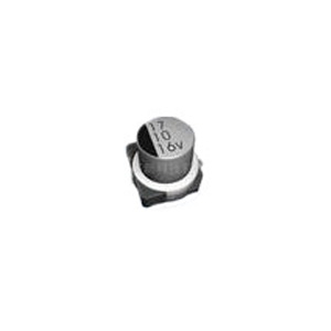
1. Designed for surface mounting on high-density circuit board.
2. Emboss carrier tape packing system is available for automatic insertion.
 |
CASE SIZE TABLE
| D |
L |
B, C |
A |
W |
E |
K |
| 4,0 |
5,4 |
4,3 |
1,8 |
0,65±0,1 |
1,0 |
0,35-0,20 to+0,15 |
| 5,0 |
5,4 |
5,3 |
2,2 |
0,65±0,1 |
1,5 |
0,35-0,20 to+0,15 |
| 6,3 |
5,4 |
6,6 |
2,6 |
0,65±0,1 |
1,8 |
0,35-0,20 to +0,15 |
| 6,3 |
7,7 |
6,6 |
2,6 |
0,65±0,1 |
1,8 |
0,35-0,20 to+0,15 |
| 8,0 |
10,2 |
8,3 |
2,95 |
0,90±0,2 |
3,1 |
0,70-0,40 to+0,20 |
| 10,0 |
10,2 |
10,3 |
3,2 |
0,90±0,2 |
4,6 |
0,70-0,40 to+0,20 |
| Unit: mm |
SPECIFICATIONS
| Item |
Performance Characteristics |
| Operating Temperature Range |
-40 to +105°C |
| Rated Working Voltage Range |
6,3 to 50V |
| Nominal Capacitance Range |
0,1 to 470μF |
| Capacitance Tolerance |
±20% (120Hz, +20°C) |
| Leakage Current |
I ≤ 0,01 CV or 3μA after 2 minutes (Whichever is greater)
C = Nominal Capacitance (μF)
V = Rated Voltage (V)
I = Leakage Current (μA) |
| tan δ (120Hz, +20°C) |
Please see the attached standard products list |
| Low Temperature Characteristics |
Measurement frequency: 120Hz
| Working Voltage (V) |
4 |
6,3 |
10 |
16 |
25 |
35 |
50 |
63 |
100 |
| Z-25°C / Z+20°C |
7 |
4 |
3 |
2 |
2 |
2 |
2 |
3 |
3 |
| 2-40°0 / Z+20°0 |
15 |
8 |
6 |
4 |
4 |
3 |
3 |
4 |
4 |
|
| Load Life |
After applying rated voltage for 1000 hours at +105°C ±2°C and then being stabilized at +20°C, capacitor shall meet
the following limits.
| Capacitance change |
±20% of initial measured value (4 W.V.: ±35%, 6,3 W.V.: ±25% Ø4 to Ø6,3) |
| tan δ |
≤ 200% of initial specified value |
| DC leakage current |
≤ initial specified value |
|
| Shelf Life |
After storage 1000 hours at +105°C ±2°C with no voltage applied and then being stabilized at +20°C, they meet the
specified value life characteristics listed above. |
| Resistance to Soldering Heat |
After reflow soldering and then being stabilized at +20°C. capacitor shall meet the following limits.
| Capacitance change |
±10% of initial measured value |
| tan δ |
≤ initial specified value |
| DC leakage current |
≤ initial specified value |
|
| Others |
JIS C - 5101 (IEC 60384) |
STANDARD RATINGS
| Voltage (Code) |
6,3V (0J) |
10V (1A) |
16V (1G) |
| Cap, (μF) |
Code |
Case Size
ØDxL (mm) |
tan δ |
Ripple
Current |
Case Size
ØDxL (mm) |
tan δ |
Ripple
Current |
Case Size
ØDxL (mm) |
tan δ |
Ripple
Current |
| 10 |
106 |
|
|
|
|
|
|
4x5,4 |
0,16 |
28 |
| 22 |
226 |
4x5,4 |
0,30 |
26 |
4x5,4 |
0,22 |
31 |
4x5,4 |
0,26 |
28 |
| 33 |
336 |
4x5,4 |
0,30 |
29 |
5x5,4 |
0,22 |
43 |
|
|
|
| 47 |
476 |
5x5,4 |
0,30 |
46 |
5x5,4 |
0,22 |
51 |
6,3x5,4 |
0,16 |
70 |
| 100 |
107 |
6,3x5,4 |
0,30 |
71 |
6,3x5,4 |
0,22 |
86 |
6,3x5,4 |
0,26 |
95 |
| 220 |
227 |
8x10,2 |
0,35 |
150 |
8x10,2 |
0,26 |
160 |
8x10,2 |
0,20 |
184 |
| 330 |
337 |
8x10,2 |
0,35 |
230 |
|
|
|
8x10,2 |
0,20 |
202 |
| 470 |
477 |
|
|
|
8x10,2 |
0,26 |
237 |
|
|
|
Maximum Allowable Ripple Current (mA rms) at 105°C 120Hz
tan δ at 20°C 120Hz |
| Voltage (Code) |
25V (1E) |
35V (1V) |
50V (1H) |
| Cap, (μF) |
Code |
Case Size
ØDxL (mm) |
tan δ |
Ripple
Current |
Case Size
ØDxL (mm) |
tan δ |
Ripple
Current |
Case Size
ØDxL (mm) |
tan δ |
Ripple
Current |
| 0,1 |
104 |
|
|
|
|
|
|
4x5,4 |
0,12 |
1 |
| 0,22 |
224 |
|
|
|
|
|
|
4x5,4 |
0,12 |
2 |
| 0,33 |
334 |
|
|
|
|
|
|
4x5,4 |
0,12 |
3 |
| 0,47 |
474 |
|
|
|
|
|
|
4x5,4 |
0,12 |
5 |
| 1 |
105 |
|
|
|
|
|
|
4x5,4 |
0,12 |
10 |
| 2,2 |
225 |
|
|
|
|
|
|
4x5,4 |
0,12 |
16 |
| 3,3 |
335 |
|
|
|
|
|
|
4x5,4 |
0,12 |
16 |
| 4,7 |
475 |
4x5,4 |
0,14 |
22 |
|
|
|
5x5,4 |
0,12 |
23 |
| 6,8 |
685 |
4x5,4 |
0,14 |
25 |
|
|
|
5x5,4 |
0,12 |
23 |
| 10 |
106 |
5x5,4 |
0,14 |
35 |
5x5,4 |
0,12 |
28 |
6,3x5,4 |
0,12 |
35 |
| 22 |
226 |
|
|
|
6,3x5,4 |
0,12 |
55 |
|
|
|
| 33 |
336 |
6,3x5,4 |
0,14 |
65 |
|
|
|
8x10,2 |
0,12 |
91 |
| 47 |
476 |
|
|
|
8x10,2 |
0,14 |
98 |
8x10,2 |
0,12 |
100 |
| 100 |
107 |
8x10,2 |
0,16 |
130 |
8x10,2 |
0,14 |
140 |
|
|
|
| 220 |
227 |
8x10,2 |
0,16 |
167 |
|
|
|
|
|
|
| 330 |
337 |
|
|
|
|
|
|
|
|
|
Maximum Allowable Ripple Current (mA rms) at 105°C 120Hz
tan δ at 20°C 120Hz |
|