|
Part Number System
| DSE |
|
105 |
|
M |
|
25 |
|
A |
|
1 |
| 1 |
|
2 |
|
3 |
|
4 |
|
5 |
|
6 |
| Series |
|
Capacitance |
|
Cap.tol.
J = ±5%
K = +10%
M = ±20% |
|
Voltage |
|
Case code |
|
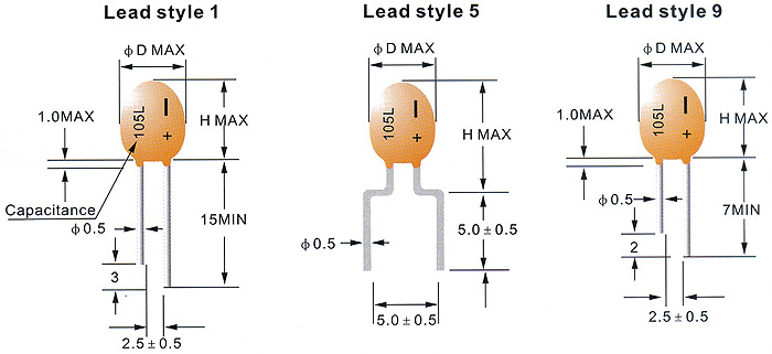
Lead style |
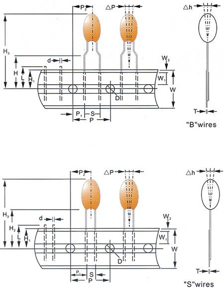
Dimensions (mm)
| Case Code |
D |
H |
| Lead Style |
| 1,9 |
5 |
| A |
3,7 |
7,0 |
9,5 |
| B |
4,0 |
7,5 |
10,0 |
| C |
4,5 |
8,0 |
10,5 |
| D |
5,0 |
9,0 |
11,5 |
| E |
5,5 |
10,0 |
12,5 |
Standard Ratings
| |
UR (V.DC) |
4 |
6,3 |
10 |
16 |
25 |
35 |
| |
UC (V.DC) |
2,5 |
4 |
6,3 |
10 |
16 |
20 |
| CR (μF) |
Code |
|
|
|
|
|
|
| 0,10 |
104 |
|
|
|
|
|
A |
| 0,15 |
154 |
|
|
|
|
|
A |
| 0,22 |
224 |
|
|
|
|
|
A |
| 0,33 |
334 |
|
|
|
|
|
A |
| 0,47 |
474 |
|
|
|
|
|
A |
| 0,68 |
684 |
|
|
|
|
A |
A |
| 1,0 |
105 |
|
|
|
|
A |
A |
| 1,5 |
155 |
|
|
|
A |
A |
B |
| 2,2 |
225 |
|
|
|
A |
B |
C |
| 3,3 |
335 |
|
|
A |
A |
B |
D |
| 4,7 |
475 |
|
A |
A |
B |
C |
D |
| 6,8 |
685 |
|
A |
A |
B |
D |
E |
| 10 |
106 |
A |
A |
B |
C |
D |
E |
| 15 |
156 |
A |
B |
B |
D |
E |
|
| 22 |
226 |
B |
B |
C |
D |
E |
|
| 33 |
336 |
B |
C |
D |
E |
|
|
| 47 |
476 |
C |
D |
D |
E |
|
|
| 68 |
686 |
D |
D |
E |
|
|
|
| 100 |
107 |
D |
E |
|
|
|
|
Electrical Characteristics
Capacitance
(μF) |
Dissipation Factor Max
(%) |
Leakage Current Max (μA) |
| -55°C |
+20°C |
+85°C |
+125°C |
+20°C |
+85°C |
+125°C |
| 0,1-1,0 |
4 |
4 |
6 |
6 |
0,01 CRUR or 0,5
(Whichever
is greater) |
0,1 CRUR or 5
(Whichever
is greater) |
0,15 CRUR or 7,5
(Whichever
is greater) |
| 1,5-6,8 |
6 |
6 |
8 |
8 |
| 10-68 |
8 |
8 |
10 |
10 |
| 100 |
10 |
10 |
12 |
12 |
The leakage current is measured at 125°C with the Uc applied.
Tape & Ammo Packing
 |
| Item |
Code |
Dimension (mm) |
| Carrier tape width |
W |
18,0 +1,0 / -0,5 |
| Hold down tape width |
W1 |
6,0±0,5 |
| Hold down tape position |
W2 |
1,0 max |
| Feed hole diameter |
D |
4,0±0,2 |
| Feed hole pitch |
P |
12,7±0,3 |
| Hole center to lead |
P1 |
"S" wires: 5,05±0,7 |
| |
|
"B" wires: 3,85±0,7 |
| Hole center to component center |
P2 |
6,35±1,0 |
| Lead wire clench height |
H |
16±0,5 |
| Hole position |
H1 |
9,0±0,5 |
| Base of component height |
H2 |
18 min |
| Component height |
H3 |
32,2 max |
| Component alignment |
DP |
0±1,3 |
| |
DH |
0±2,0 |
| Lead spacing |
S |
"S" wires: 2,5 +0,6 / -0,1 |
| |
|
"B" wires: 5,0 +0,6 / -0,1 |
| Lead diameter |
D |
0,5±0,05 |
| Length of snipped lead |
L |
11,0 max |
| Carrier tape thickness |
T |
0,5±0,1 |
|
 |
| Case Code |
A, B, C |
D |
E |
| QTY (PCS/box) |
3000 |
2500 |
2000 |
|
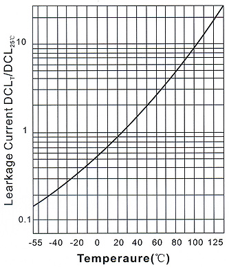
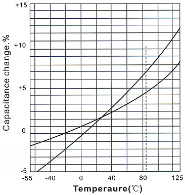
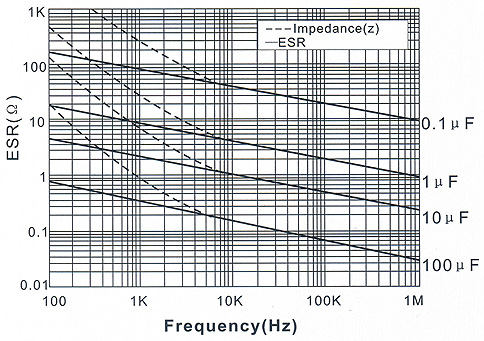
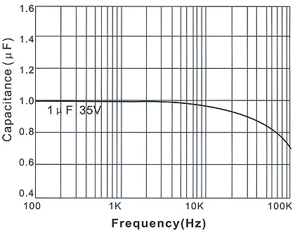
Typical Characteristic Curve
|