Products:
Battery Holders
Capacitors
Connectors
Gas tubes
Heat Sinks
ICs >> STM32 microcontrollers
LCD Module
LED Display
LED Lens
LED Lights
LED Module
Materials
Miniature Speakers
Plastic & Hardware
Plastic profiled housings on a standard electric DIN rail
Potentiometers & Encoders
Resistors
Power Supplies
Power supply filters
Quartz Crystal
Switches
Test Probes
Thermistors
Varistors
|
|
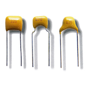
Capacitors /
Radial Leaded MLCC
 |
|
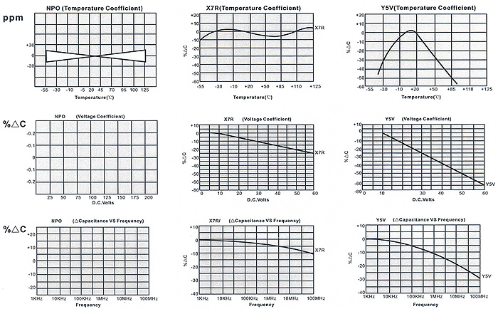
The choice of dielectric is largely determined by the temperature stability required
NPO (COG)
Ultra Stable Class I dielectric, with negligible dependence of electrical properties on temperature, voltage, frequency and time. Used in circuits requiring stable performance.
X7R (2X1)
Stable Class II dielectric, with predictable change of properties with temperature, voltage, frequency and time. Used as blocking, coupling, by-passing and frequency discriminating elements. This dielectric si ferroelectric and offers higher capacitance ranges than class 1.
Y5V (2F4) Z5U
General Purpose Class II dielectric with highest dielectric constant and greater variation of properties with Temperature and test conditions. Very high capacitance per unit volume and suited for bypass and coupling application as well as filtering, transient supression blocking, and charge storge application. |
CAPACITANCE VALUE & TOLERANCE
Determined by circuit requirements, Note that chip prices decrease with lower capacitance value and looser tolerances.
CAPACITOR TERMINATION
Termination choice is largely determined by the chip attachment method Nickel barrier is recommended for units exposed to repeated solder cycles, to preclude leaching fo the termination. Silver is used on units to be lead attached, as the more ductile silver minimizes thermal cycling hazards.
VOLTAGE
Determined by circuit requirements. Units are designed to exceed the withstanding voltage specification, i.e., The user need not incorporate an additional salty margin.
PACKAGING
Units are available in bulk, some sizes on tape & reel. Specify if reeled. |
GENERAL SPECIFICATIONS
| |
CC41 CC4 CC42
(NPO) |
CT41 CT4 CT42
(X7R) |
CT41 CT4 CT42
(Y5V, Z5U) |
| Capacitance Range |
0,1 PF - 0,22 μF |
100 PF - 2,2 μF |
1000 PF - 4,7 μF |
| Temperature Coefficient |
0±30PPm/°C
(-55°C...+125°C) |
±15°C
(-55°C...+125°C) |
30°C~80% (-25°C...+ 85°C)
22°C~56% (+10°C~ + 85°C) |
| Insulation Resistance |
C≤10nF R>10000MΩ
C>10nF C.R>100S |
C≤25nF R>4000MΩ
C>25nF C.R>100S |
| Dielectric Test Voltage |
2,5xWVDC |
| Dissipation Factor |
0,15%max ±0,2
(20°C, 1MHZ, 1VDC, 75%) |
2.5%max ±0,2
(20°C, 1KHz, 1VDC, 75%) |
3.5%max ±0,2
(20°C, 1KHz, 0,3VDC, 75%) |
| Voltage Ratings |
25, 50, 63, 100 V DC |
25, 50, 63 V DC |
| Capacitance Tolerances |
B = ±0.1PF
C = ±0.25PF
D = ±0.5PF
F = ±1%
G = 2%
J = ±5%
k = 10%
M = ±20%
(B.C.D for C<10PF) |
K= ±10%
M= ±20%
S = +50% / -20% |
M = ±20%
S = +50% / -20%
Z = +80% / -20%
P = +100% / -0% |
| Life Test (1000 hours) |
200% rated voltage at +125°C |
150% rated voltage at +85°C |
| Solderabillity |
GB9324-88 4,11 |
| Resistance to Soldering Heat |
GB9324-88 4,10 |
| Shock |
GB2693-90 4,17 |
| Temperature Cyling |
GB9324-88 4,12 |
| Moisture Resistance |
GB9324-88 4,14 |
| Termination adhesion strength |
GB9324-88 4,9 |
| Environment testing |
GB9324-88 4,13 |
TYPICAL CHARACTERISTICS
|
|